
Frequently Asked Questions
General Questions
Many of our products have an online demonstration available. You can submit a demo request from the product page.
We offer online training for all our products.
The serial number is located on the device and preceded by the letters SN. View your product below to determine the location of the serial number. Note the example shown may not be an exact match to your device.
Universal ECG™
Serial numbers are located on the hub.
ABP Monitors
Serial numbers are located at the back of the device.
Orbit™ Spirometer
Serial numbers are located at the back of the device.
Q200 Holter
Serial numbers are located beneath the battery.
VectraplexECG
Simply, it is a color coded index number that measures the degree of di-polarity of the cardiac electrical field. The cardiac electrical field of a healthy patient is primarily di-polar1, while occurrence of myocardial injury leads to the appearance of a multi polar cardiac electrical field2. A CEB® greater than 94 indicates an abnormal condition and further clinical assessment is necessary.
It is used as an additional tool to alert clinicians that a patient may have an abnormal condition that requires additional assessment.
References
1. Schmitt, OH AM Heart J. 1953;45:416-428
2. Tysler – J Electrocardiol. 2013 Jul-Aug;46(4):284-8. Doi:10.1016/j.electrocard.2013.03.014. Epub 2013 Apr 28.
Recommended Reading: Automated Analysis of the 12-lead ECG in the Emergency Department: Association Between High-sensitivity Cardiac Troponin I and the Cardiac Electrical Biomarker. Larisa G. Tereshchenko, MD, PhD,* David Gatz, BS,* Albert Feeny,† and Frederick K. Korley, MD‡
Step 1. Go to the Software Download page.
Step 2. Scroll Down and click Activate Now under the VectraplexECG section.
*For Windows 7 Please click “How to Activate Windows 7” before continuing. These instructions are ONLY for Windows 10 since Microsoft customer service no longer provides Windows 7 technical support.
Step 3. You will be directed to the Log In to Your Account page. Enter the Login/License ID and Login/License Password provided on the back of this page (Not your email).
*Please note that the Login ID/License ID and Login/License Password are case sensitive. Disregard Existing Customer.
Step 4. You will be directed to the Customer Information page. Fill out your facility information, click Submit when finished.
Step 5. You will be directed to the License Portal Home page. Under the Welcome bar, click Downloads.
Step 6. You will be directed to the Downloads page. Click Download to continue.
Step 7. You will be directed to the Box Website. Hover your mouse over to the very right of Windows 10 VECG & Office Medic Installer.iso and Click the three dots that appear with the tag pop up More Options. Click the Download button that drops down.
Step 8. The Your Download is In Progress window will appear, no action is required, Click X.
Step 9. Your Installer will pop up on the top or bottom of your window, depending on your browser. Double Click the Installer, WAIT TILL IT’S DOWNLOADED to continue.
Step 10. Your Files window will appear. Scroll down and Click DVD Drive… Scroll down, locate, and Double Click Setup.
*There will be several Setups, ensure that the one you select matches the Image.
Step 11. The User Account Control window will appear, click Yes when asked “Do you want to allow this app from VectraCor to make changes to your device”. *Image not shown
Step 12. The Choose setup language window will appear. Select your language of choice and Click Next.
Step 13. The Welcome to the InstallShield Wizard window will appear. Click Next.
Step 14. The Setup Type window will appear, select VectraplexECG or VetraplexECG and Office Medic and Click Next.
Step 15. The Choose Destination Location window will appear,Click Next.
Step 16. The Set Program Options window will appear, click Local Database or click Network Database, Click Next.
Step 17. The Please Choose Defaults window will appear, click United States of America or International, Click Next.
Step 18. The Setup Status window will appear, Wait for download, Click Next.
Step 19. The Welcome to the Device Driver Installation Wizard! window will appear,Click Next.
*Please disregard the windows of code behind your Installation Wizard windows, do not close them out.
Step 20. The Completing the Device Driver Installation Wizard window will appear, after the checkmarks under Driver Name turn green and the Status states Ready to use, Click Finish.
*Please disregard the windows of code behind your Installation Wizard windows, do not close them out.
Step 21. The Installshield Wizard Complete window will appear, Click Finish.
Step 22. You will be directed to the VectraplexECG System with CEB. The VectraplexECG window will appear, click Activate Vectraplex.
Step 23. The VectraplexECG Activation window will appear, click Activate VectraplexECG Online.
Step 24. The License ID and Password window will appear, Type in your Login/License ID and Login/License Password provided below, Click Continue Located on the bottom right corner of the window.
*Please disregard the Where is my License ID?
Step 25. The VectraplexECG Activation window will appear, Once you’ve received Product Activation Successful Click Continue, Located on the bottom right corner of the window.
Step 26. Test your new VectraplexECG software to ensure proper download.
* If the program is not loading please contact our customer support team at QRSsupport@vectracor.com, or give us a call at (973) 904-0444 Ext. 2
Office Medic
You may have an older version of Office Medic that is not validated to work with Windows 10. See how to upgrade to the latest version.
Installation Instructions
Install the software prior to connecting the medical device to the PC.
- Verify your PC meets the system requirements and that you are logged in as the administrator.
- Close all other programs.
- Register your product(s) using the Products Registration page to receive software updates (included under warranty)
- Click on the link, select Download and select Save to save the zip file to your hard drive. (download files) *Email QRSsupport@vectracor.com for password
- Unzip the file and double-click on Setup.exe. Follow the prompts for installing the software.
Step 1. Go to the Software Download page.
Step 2. Scroll Down and click Download Now under the Office Medic section.
* For Windows 7 Please click “How to Activate Windows 7” before continuing. These instructions are ONLY for Windows 10 since Microsoft customer service no longer provides Windows 7 technical support.
Step 3. You will be directed to the Log In to Your Account page. Enter the Login/License ID and Login/License Password provided on the back of this page (Not your email).
*Please note that the Login ID/License ID and Login/License Password are case sensitive. Disregard Existing Customer.
Step 4. You will be directed to the Customer Information page. Fill out your facility information of your facility information, click Submit when finished.
Step 5. You will be directed to the License Portal Home page. Under the Welcome bar, click Downloads.
Step 6. You will be directed to the Downloads page. Click Download to continue.
Step 7. You will be directed to the Box Website. Hover your mouse over to the very right of Windows 10 VECG & Office Medic Installer.iso and Click the three dots that appear with the tag pop up More Options. Click the Download button that drops down.
Step 8. The Your Download is In Progress window will appear, no action is required, Click X.
Step 9. Your Installer will pop up on the top or bottom of your window, depending on your browser. Double Click the Installer, WAIT TILL IT’S DOWNLOADED to continue.
Step 10. Your Files window will appear. Scroll down and Click DVD Drive… Scroll down, locate, and Double Click Setup.
*There will be several Setups, ensure that the one you select matches the Image.
Step 10a. Your Files window will appear. Locate and Click the Extract All Files Tab.
Step 10b. An Extract Compressed (Zipped) Folders Window will appear, click Extract.
Step 10c. Your Files window will appear. Click Windows 7 VECG
Step 10d. Your Files window will appear. Scroll down, locate, and Double Click Setup.
*There will be several Setups, ensure that the one you select matches the Image.
Step 11. The User Account Control window will appear, click Yes when asked “Do you want to allow this app from VectraCor to make changes to your device”. *Image not shown
Step 12. The Choose setup language window will appear. Select your language of choice and Click Next.
Step 13. The Welcome to the InstallShield Wizard window will appear. Click Next.
Step 14. The Setup Type window will appear, select VetraplexECG and Office Medic and Click Next.
Step 15. The Choose Destination Location window will appear, Click Next.
Step 16. The Set Program Options window will appear, click Local Database or click Network Database, Click Next.
Step 17. The Please Choose Defaults window will appear, click United States of America or International, Click Next.
Step 18. The Setup Status window will appear, Wait for download, Click Next.
Step 19. The Welcome to the Device Driver Installation Wizard! window will appear,Click Next.
*Please disregard the windows of code behind your Installation Wizard windows, do not close them out.
Step 20. The Completing the Device Driver Installation Wizard window will appear, after the checkmarks under Driver Name turn green and the Status states Ready to use, Click Finish.
*Please disregard the windows of code behind your Installation Wizard windows, do not close them out.
Step 21. The Installshield Wizard Complete window will appear, Click Finish.
Step 22. Close out VectraplexECG and open up Office Medic to test your new software to ensure proper download.
* If the program is not loading please contact our customer support team at QRSsupport@vectracor.com, or give us a call at (973) 904-0444 Ext. 2
Universal ECG
The Universal ECG is DISCONTINUED
Yes. Please download the Universal ECG How-To Guide.
The interpretation program developed by Cardionics SA in conjunction with the Catholic University of Louvaine (UCL) in Belgium. Download the Universal ECG Algorithm brochure for additional information.
• Heart Rate
• P Duration
• PR Interval
• QRS Duration
• QT Interval
• QTc Interval
• P Axis
• QRS Axis
• T Axis
You also get a detailed count of the amplitude, slope, and duration of each lead at the P, Q, R, S and T.
No, the interpretative algorithm does not provide a specific pediatric interpretation; the algorithm has been validated at ages above 16.veniam, quis nostrud exercitation ullamco.
Yes, you can edit the interpretation and also add comments for each test.
The Universal ECG does not have any moving parts so it does not require annual maintenance contracts for calibration/servicing. Like any ECG, over time the lead wires will need to be replaced. The lead wires should be handled gently to ensure maximum life is met. The lead wires should not be pulled on, twisted,wrapped in a ball, or caught in the wheels of a cart.
> 12 ounces
Limb Leads – 1 meter
Chest Leads – 0.6 meter
Yes, the Universal ECG has a direct USB connection.
1.8 meters
Yes, any electrode system will work that connects snugly to the ECG lead wire connectors (4mm “banana” plugs).
Patient leads are isolated from system and operator with 4kV protection.
0.05 to 175Hz, +/-3dB
SCP format. SCP-ECG, Standard communications protocol for computer assisted electrocardiography, is a file format for ECG traces, annotations and metadata. It is defined in the joint ANSI/AAMI standard EC71:2001 and in the CEN standard EN 1064:2005.
Our PC-based ECG integrates with all EMRs that can import PDF, JPEG or TIFF files, which accounts for nearly all EMRs on the market. If a more direct integration is desired, contact Customer Care for more information.
ECGs can be viewed in real-time for an unlimited period of time. Up to 15 minutes of ECG trace can be paused and reviewed. Once SAVE is selected, a 10-second recording is saved and interpreted.
Raw file format average size – 90 kb
PDF average size – 700 kb
Download the Sample Report for page references listed below.
- 3×4 Simultaneous – shows a 2.5 second simultaneous segment of ECG data for each of the leads, as well as the full 10 seconds of captured data for a single lead. (See Page 1 of Sample Report)
- 3×4 Sequential – shows a sequential sample of 2.5 seconds of ECG data from each of the 12 channels. The format has three rows of four channels of data, with a single channel at the bottom of the page. (See Page 2 of Sample Report)
- Average Complexes – shows an average complex for each of the 12 channels. It also includes a single channel 10-second trace.
- 6×1 Report – features the full 10 seconds of data from each of the 12 leads. (See Pages 4-5 of Sample Report)
- 6×2 Report – features 5 seconds of data from each of the twelve leads. (See Page 3)
- Measurements Report – features the amplitude of the various parts of the wave in mV for each of the 12 channels, the slope of the ST segment (in millimeters/s) and the duration (in milliseconds) for Q, R, S, R’ and S’. (See Page 7)
- Zoom & Average Zoom Reports – The zoom view report can only be created by clicking the ZOOM button from the ECG Diagnostic Window. The Average Zoom Report prints an exploded view of a single QRS complex with the software’s measurement of the following quantities: P duration, PR duration, QRS duration and QT duration. (See Pages 8-9)
Most printers should work with the Universal ECG.
All analyzed reports are printed in landscape. Printouts of the real-time window can be done in either portrait or landscape.
Only if your printer handles thermal paper.
For a red grid background it is recommended you use a color printer using plain paper.
It is possible with the installation of a Windows-compatible fax or e-mail software.
3-year hardware warranty on device – 1 year warranty on lead wires and PC connection cable. For additional details, visit the Hardware Warranty page within Customer Care.
Send the broken cable(s) to a certified VectraCor service center to repair the broken lead wire(s). Request an RMA Number here.
No, you should only clean the cable with a clean cloth moistened with water. Alcohol will damage the plastic over time and may cause the case to crack.
Orbit Spirometer
The VectraCor spirometers are pre-calibrated, as are the mouthpieces. VectraCor spirometers do not require calibration, however, the software does allow for calibration checks in the field with a 3-liter calibration syringe. If you believe your device is out of calibration after testing several mouthpieces, please contact QRS Customer Care.
Yes. The Orbit directly connects to the PC via a USB cable.
Mouthpieces are single patient use only but can be used up to 20 times over a 10 day period for that patient, if fabric does not become contaminated. The patient should open, handle and dispose of his/her own mouthpiece and should return it to its plastic bag to avoid contamination if future use is anticipated. Never use the same mouthpiece on different patients.
Mouthpieces are single patient use only. The patient should open, handle and dispose of his/her own mouthpiece and should return it to its plastic bag to avoid contamination if future use is anticipated. Never use the same mouthpiece on different patients. See the next question for additional details.
Air doesn’t go down the tube; only pressure travels through the tube. There is a static pressure column created between the end of the mouthpiece and the pressure transducer inside the spirometer. The patient’s exhalation follows the path of least resistance, the vents on the side of the mouthpiece, thereby preventing moisture from entering the pressure tube.
To illustrate take a pressure tube that can be discarded. Attach the pressure tube to the mouthpiece and cover the opposite end of the pressure tube with your finger. Breathe through the mouthpiece. Notice the lack of moisture in the pressure tube and repeat. Moisture will never be present. This demonstrates that if used properly the pressure tube will not become contaminated. If a patient covers the vents on the mouthpiece or uses the pressure tube when it is not properly connected to the spirometer, the pressure tube must be replaced.
The pressure tube can be reused on multiple patients (no quantity limit). QRS suggests replacing the pressure tube if condensation forms in the tube or if the tube is kinked or becomes occluded. If a patient covers the vents on the mouthpiece or uses the pressure tube when it is not properly connected to thespirometer, then the pressure tube must be replaced. Store the pressure tube in a cool dry place to avoid condensation forming in the tube.
Nose clips are not required for spirometry tests, however the ATS Guidelines recommend using a nose clip to prevent air leaking out of the nose during the test. To get the most accurate results, no leaking can occur.
FVC, FEV0.5, FEV1, FEV6, FEV3, FEV1/FEV6, FEV1/FVC, FEV3/FVC, PEFR, PEFT, FEF25%, FEF50%, FEF75%, FEF25-75%, FIVC, FIV0.5, FIV1, FIV3, FIV1/FIVC, FIV3/FVC, PIFR, FIF50%, FIF25-75%, FIF .2-1.2%, FVC/FIVC, Extrapolated Volume, EOTV, FET, MVV, RR, MTV, SVC
• FVC
• Pre/Post Testing
• Flow Volume Loop
• MVV
• SVC
FVC/SVC Predictors:
- Adult: Crapo ’81, Cherniack ’72, Morris, Knudson ’83, Roberts ’91, NHANES III ’99, ECC/ERS/Quanjer ‘93
- Pediatric: Hsu ’79, Knudson ’83, Polgar ’71, Warwick ’77, NHANES III ’99, Zapletal ’87, Wang ’93, Quanjer ‘95
MVV Predictors:
- Adult: Cherniack ‘72
- Pediatric: Polgar ’71, Zapletal ‘87
Lung age is equal to the predicted FEV1 that matches the patient’s actual FEV1. Lung age is calculated for patients between 20-84 years old. If anyone falls outside this age range then the Lung Age will not be calculated. Also if anyone’s calculated Lung Age falls outside of 20-84 years old then a Lung Age will not be displayed by the software.
*Note: lung age may differ based on the predicted equation chosen. Reference: Morris JP, Temple W.; Spirometric “lung age” estimation for motivating smoking cessation. Prev Med. 1985 Sep: 14)5):655-62. Age Range: 20-84.
Your hardware relies on drivers that ship with the Office Medic software.
Opti 24-hr ABPM
The Opti monitor is is DISCONTINUED
To turn ON, press and hold the start/stop button until you hear a series of 3 quick beeps. To turn OFF, press and hold the start/stop button until you hear a series of five beeps.
The OptiFit cuffs are designed to meet the AAMI (Associate for the Advancement of Medical Instrumentation) clinical standards for blood pressure cuffs. These standards were devices in order to ensure adequate pressure on the artery of the upper arm, which is necessary to produce an accurate blood pressure measurement. If a cuff is used on an arm larger that the specified range, the resulting reading will be falsely high. If a cuff is used on an arm that is smaller than the specified range, the resulting reading will be falsely low.
The following cleaning methods have been applied 20 times to the cuff without any apparent negative effects:
- Medical Disinfectant Spray – The cuff may be sprayed with a mild disinfectant solution, rinsed with distilled water, and line dried. Ensure that no liquid enters the bladder tubing.
- Medical Disinfectant Wipe – Use a mild disinfectant wipe and thoroughly wet cuff surface and line dry.
- Machine Wash – Remove bladder to machine wash the cuff shell. Machine wash warm (50-130° F, 10-54°C) with a mild detergent and line dry.
The Opti-Insight software will run on the latest Operating Systems. Version 3 – Supported on Microsoft Windows 98, 2000, ME, XP. Version 2.x – Supported on all Microsoft Windows Operating Systems 95 and above.
The Opti-Insight software can export data to be used in a spreadsheet or database. Use the File >> Export function, Opti-Insight can be exported into an ASCII text file for use by most spreadsheet and database programs. The export function is flexible enough to allow for only data of interest and be exported and various of delimiters can be chosen.
All files from the Opti-Insight software products can be sent via email and be opened with the corresponding Opti-Insight program that originally downloaded them. Also, all Opti-Insight software products can send reports over a modem to a fax machine when used with a PC with a fax-printer driver installed.
Opti-Insight has a one button operation to create patient reports in PDF format. PDF files of paitent reports can then be placed into the paitent’s folder for most EMR systems. This allows viewing of a patient’s report without the need for Opti-Insight.
Check the hardware settings under CONFIGURE, then PREFERENCES. Select a configuration to EDIT. Serial Port will show all ports available on the computer.
48hr ABPM
The 48hr ABPM is DISCONTINUED
This is an error code which can indicate three possibilities:
- Unsuccessful measurements
- E-1 – too much movement by the patient: instruct patient to move less
- E-2 – manually aborted measurement: ask patient about the cause of abort
- E-3 – batteries run down during measurement: replace batteries
- E-4 – batteries were replaced during measurement: no action necessary
- E-8 – preset pressure limit exceeded: use higher preset limits
- E-9 – static discharge, temporary disturbance: no action needed if it is not frequent. If this error happens frequently then please contact your local distributor’s support team.
- Cuff related errors (31-34)
- Check if the cuff is properly connected to the device and properly put on the patient’s arm.
- If you have a spare cuff then connect it to the device and test it.Contact your local distributor’s support team if the error is still present.
- Device errors
- E-90 – if this is a constant error, then please return the device to your local distributor’s support team
- E-99 – check if the cuff size is properly selected in the software. Contact your local distributor’s support team if the error is still present.
Please connect the device to the PC and program it. The clock should self adjust
to the correct time.
V300 Holter Monitor
VectraCor Silver Cardiac Holter Software, VectraCor Gold Cardiac Holter Software, and VectraCor Platinum Cardiac Holter Software are compatible with Microsoft Windows XP Professional, Windows XP Home and all other versions of the operating system back to Windows 98 Second Edition.
Virtually any Windows based PC. We recommend as a reasonable minimum a Pentium class computer with 128 Megabytes of RAM, 2 available USB ports, an SVGA monitor, 2-Button Mouse, 300 dpi Windows supported printer, a CD-ROM drive (to install the software), and at least 200 Megabytes of available Hard Disk space (for the software and several patient studies).
Yes, simply remove the patient cable from the monitor. The screen will change to read: “Suspend”. Hold down the leftmost button for approximately 6 seconds. The screen will change to read: “End Mon? No / Yes”. Press the button below “yes”. The screen will now read: “Creating Report”. When the screen changes to read: “Monitor Done”, the report is completed and ready to be downloaded.
In a very small percentage of monitoring sessions (less than 5%), the flash memory card will fill up with data before the end of the monitoring session. Any combination of several factors may contribute to this. There is no problem with the operation of the device, and the next monitoring session will not likely repeat this message. The monitor will detect that its memory capacity is full and stop itself early and create the report. Your patient’s data should be ready to download. Usually, the report will be only slightly less than the full 24 hours.
The “MC FULL” is an infrequent event that indicates one or more of the following conditions are present:
- Poor Hook-up Quality leading to excessive artifact in the recording (Initial Signal Quality on one or more leads in the “Red Zone”)
- Loss of Electrode
- Intermittent break in a lead wire
- Patient in an electrically “noisy” environment: sleeping under an electric blanket, exposed to microwaves, strong electro-magnetic fields, etc.
- Sustained high heart rate (18 plus hours over 175 BPM)
- Unusually large amount of complex arrhythmia
- Paced patient with some combination of the above
- 3-channel recording with some combination of the above
The first two conditions are easily controlled with consistent attention paid to the proper preparation of the patient, selection of electrode sites and use of high-quality Holter electrodes. Lead wires should be carefully cleaned and inspected after each use. The patient should be instructed to avoid electrically noisy environments as much as possible for the duration of the monitoring period. The other conditions are generally outside of your control, and quite rare.
An MC Full condition does not mean that the memory card needs to be erased or is no longer usable. It is simply an indicator that during the monitoring session one or more of the above conditions were present.
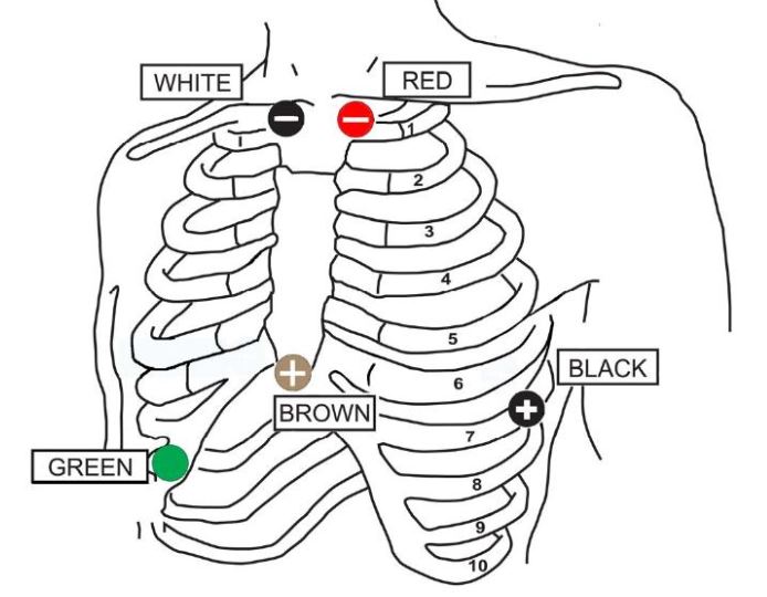
Hookup Diagrams
| Channel | Electrode | Position |
|---|---|---|
| Channel 1 CM – V₅ | White (-) Red (+) | Right Manubrial Border of Sternum 2 cm Right of Xiphoid Process on the Rib Margin |
| Channel 2 CM – V₁ | Black (-) Brown(+) | Left Manubrial Border of Sternum Left Anterior Axilliary Line Sixth Rib |
| Green (Ground) | Lower Right Rib Margin Over Bone |
| Channel | Electrode | Position |
|---|---|---|
| Channel 1 Modified V₅ | White (-) Red (+) | Over First Right Rib Over Sixth Left Rib |
| Channel 2 Modified V₁ | Black (-) Brown(+) | Over First Left Rib Over Fifth Right Rib |
| Green (Ground) | Over Right Lower Border of Rib Cage |
If Amplitude of complexes is less than 1mv:
In Channel 1: Position new electrode closer to apex than current Brown electrode (toward patient’s Left – closer to V2 position). DO NOT USE SAME ELECTRODE, then move Brown wire to new electrode – if amplitude improves, remove first electrode.
In Channel 2 or 3: Position new electrode closer to apex than current Black electrode (toward patient’s Right – closer to V4 position). DO NOT USE SAME ELECTRODE, then move Black wire to new electrode – if amplitude improves, remove first electrode.
** Alternate Lead Placement Configurations may be used depending on specific aspects of EKG waveform being sought by the physician. Examples of these may be found in the Recorder’s Operator Manual for reference
| Channel | Electrode | Position |
|---|---|---|
| 3- | White | Right Manubrial Border of Sternum, below Clavicle |
| 1-, 2- | Red | Left Manubrial Broder of Sternum, below Clavicle |
| 2+, 3+ | Black | Left 7th Rib, Midway betweeen Axillary line and Nipple line |
| 1+ | Brown | Base of Sternum, center of body, above Diaphragm |
| Reference | Green | Lower Right Rib Margin Over Bone |
| Channel | Electrode | Position |
|---|---|---|
| Channel 1 CM – V₅ | White (-) Red (+) | Right Manubrial Border of Sternum 2 cm Right of Xiphoid Process on the Rib Margin |
| Channel 2 CM – V₁ | Black (-) Brown(+) | Left Manubrial Border of Sternum Left Anterior Axilliary Line Sixth Rib |
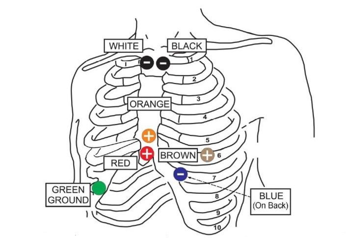
| Channel 3 CM – V₃ | Blue (-) Orange(+) | Center of the Back Lower Sternum Above the Diaphragm |
| Green (Ground) | Lower Right Rib Margin Over Bone |
If Amplitude of complexes is less than 1mv: (Shows steady Red LED on Trillium 1000-4000 recorders)
In Channel 1: Position new electrode closer to apex than current Red electrode (toward patient’s Left – closer to V3 position). DO NOT USE SAME ELECTRODE, then move the Red wire to new electrode – if amplitude improves, remove first electrode.
In Channel 2: Position new electrode closer to apex than current Brown electrode (toward patient’s Right – closer to V4 position). DO NOT USE SAME ELECTRODE, then move the Brown wire to new electrode – if amplitude improves, remove first electrode.
In Channel 3: Position new electrode closer to apex than current Orange electrode (toward patient’s Left – closer to V2 position). DO NOT USE SAME ELECTRODE, then move the Orange wire to new electrode – if amplitude improves, remove first electrode.
** Alternate Lead Placement Configurations may be used depending on specific aspects of EKG waveform being sought by the physician. Examples of these may be found in the Recorder’s Operator Manual for reference.
| Channel | Electrode | Position |
|---|---|---|
| Channel 1 V₂ (Modified) | White (-) Red (+) | Right Manubrial Border of Sternum Lower Sternum above the Diaphragm |
| Channel 2 V₅ (Modified) | Black (-) Brown(+) | Left Manubrial Border of Sternum Left Anterior Axilliary Line Sixth Rib |
| Channel 3 “Z-Axis Lead” | Blue (-) Orange(+) | On the Back, Base (Inferior Angle) of the Left Scapula Right of the Xiphoid Process on the fifth Rib Margin |
| Green (Ref. or Ground) | Lower Right Rib Margin Over Bone |
Q200/HE Recorder
The Q200/HE Recorder is DISCONTINUED
Flashcards from other vendors may be used in the recorders, however, because some card manufacturers provide memory cards which draw too much battery current, some cards may cause the batteries to be depleted prematurely resulting in the Holter stopping early. Because of this, we recommend that you first test cards purchased from another vendor for a greater amount of time than the expected use. Also, before using a new flashcard, you will need to format the card using the INITIALIZE function in the Holter program.
No. These are not supported in the Q200/HE recorder.
A problem with your recordings may be the result of a cable that is not functioning properly because it is damaged or old. First check to see if your cable is damaged or badly worn, if so, it should be replaced. Even if the cable appears to be fine, a cable that needs replacing may result in one or more of the following issues:
- Poor quality hook-ups – any or all channels are artifact
- Low voltage QRS
- Lead quality test always below 3
By properly caring for your cables you can keep them in a good working condition for an extended period of time.
- Don’t bend or wrap wires around recorder
- Clean leads between uses with metricide or bleach
- Keep electrodes at the right temperature.
- Ensure electrodes are new – not dried out or rusted.
- Check cable for breakage between uses.
Remove and erase the card using the Holter program and reinsert. If this does not solve the problem, please call your distributor or check out our Customer Care page for further troubleshooting or an RMA#.
The shortened recording times may occur because the Holter is shutting down due to a depleted battery. One cause of premature battery depletion is flash/memory cards that draw too much current. The memory card provided by VectraCor has been tested to meet the specification of the Holter unit, drawing a low current to maximize battery life. There are a number of memory card manufacturers and vendors who provide memory cards with much greater current draw. Flash/memory cards vary greatly with respect to the current that they use, even when purchased from the same manufacturer. They still meet the specification for the card, but achieve it at the expense of very high current. This high current will deplete the battery in less than the desired recording time. Lexxar and SanDisk are two manufacturers that have been tested and are recommended for use with the Q200/HE. If you choose to purchase cards from other manufacturers, test the card for a greater amount of time in the Q200/HE recorder than the expected use to determine its effect on battery life.
The patient’s Holter data is stored in the recorder on a removable SD card. To store 24 hours in normal mode, 28 megabytes (MB) is required. To store 24 hours in high mode, 56 MB are required, and a 14-day recording in high resolution mode would require about 760 MB. To view the actual size of the flash.dat file on your card, put the card in the reader and view the file when you are prompted to do so. If you have enough capacity on your SD card, but are getting short recordings, the flash.dat file on your SD card may have been corrupted. You can fix this problem by reformatting and re-initializing your card. The instructions for doing this can be found in the Holter LX Analysis International User Guide starting on page 4. If you sometimes do recordings that are more than 48 hours, be sure to choose the option that does not specify “less than 48 hour recording.” Also, be sure to allow the process to complete before removing the SD Card from the reader.
Gently press inward on the SD card to release. The card will pop-out. Never pull the card out – it may damage the recorder.
To use the Q200/HE in Holter mode, you must have some level of Holter LX Analysis software. The levels are Enhanced, Enhanced Plus and Pro. Each level offers different capabilities; download the Holter LX Analysis Features Matrix learn more about each level of software. To use the Q200/HE in telephonic Event mode (this is the most common method of transmitting event recordings), you can use ANY event software. However, using our LX Event software makes life a bit easier and guarantees that the telephonically transmitted data with patient header information will be correctly/automatically received by the receiver. To use the Q200/HE in data card Event mode (this special mode is available only to users of our hardware and software), you must use our LX Event software.
When entering the characters for the Patient ID, press the ENTER button to advance from one character to the next. If you need to backspace, hold down the ENTER key for a bit longer than normal. When you have entered the complete Patient ID, finish by pressing the EVENT button. Once you have entered the Patient ID and completed the process by pressing and holding the EVENT button, the only way to change the Patient ID is to remove the battery and start over again. See, “To Start the Recorder for Holter”, on the Q200/HE Hook-Up Guides.
| SILVER | GOLD | PLATINUM | |
Standard 24-Hour Holter Reporting | ✓ | ✓ | ✓ |
Color Coded Arrhythmias | ✓ | ✓ | ✓ |
7-Day Holter Reporting | ✓ | ✓ | |
Pacemaker Analysis | ✓ | ✓ | |
PDF Output | ✓ | ✓ | |
Superimposition | ✓ | ✓ | |
High Rate Algorithm | ✓ | ✓ | |
Q-T and P-R Interval Analysis | ✓ | ||
Beat-by-Beat Output | ✓ | ||
HRVf Analysis | ✓ |
Electrodes that are dried out will cause this message to appear and should be replaced. However, some types of electrodes, including the new, high-impedance gel formulations, cause the “Lead Loose” message to be displayed even though there is not an issue with the signal quality. If you are receiving an adequate signal, you can turn the “Lead Loose” message off under “Settings.”
After deleting the events by pressing either arrow for 3 seconds, reboot the recorder by removing and reinserting the battery. Then, interrupt the 15-second countdown by pressing ENTER, down arrow, up arrow and the EVENT button. Now press ENTER and go to the General Settings menu where you can change the recording type from Event to Holter. The Q200/HE Hook-Up Guides in your hardware kits also tell you how to start your recorder for Holter or Event.
First, make sure that the card reader is plugged in and that a card is inserted correctly into the reader. Second, it may be that your computer can no longer see your Card Reader. To fix this, remove card reader plug from the computer and plug into a different USB port on the computer. Third, try turning off and restarting your computer. If you still cannot see the Flash file, your reader may need repair. Try using another reader if available, or call your distributor or check out the Customer Care page for further assistance.
This means that there are files on the card other than flash.dat. You must remove these files using Windows by clicking on “Start” and then “My Computer”. Double-click on the appropriate Removable Disk to see all of the files on the card. Delete all files except for flash.dat.
Installation instructions were included in your software kit and also can be found in the Holter LX Analysis Software Manuals. If you encounter problems in the Installation process, contact your distributor or VectraCor Customer Care.
Refer to the Holter LX Analysis manuals for instructions on how to customize the software using the CONFIGURATIONS feature.
Back-ups should be done on a regular basis as determined by your organization. In order to do backups, your computer must have a CD drive. Instructions on how to back up your software is included in the manual.
If the QRS complexes are very small, some of them can be missed so that the software identifies false positive pauses. If that happens, go to REVIEW > CALIBRATION, move the calibration lines as close to the baseline as possible, and press DONE. The software will reanalyze the signal using a higher gain and find the small QRS complexes.
In order to set up an alternate language in Holter LX Analysis, you will need to do the following:
- Install software on your desktop
- Open the Utilities screen and change the language to what you desire.
- Open Holter LX Analysis and go to File > Preferences > Configurations.
- Save one more new configuration by copying the “Standard” and saving the new configuration with a name of your choice.